This definitive surgical technique guide details the application of the LYNXVET Rod Locking System for canine tibial fracture fixation. Incorporating Biological Osteosynthesis (BO) principles and angular-stable rod-locking technology, the guide provides comprehensive coverage from case selection and preoperative planning through surgical execution and rehabilitation protocols. Navigate using the table of contents for targeted access to specific procedural components.
1. Introduction
Tibial fractures represent one of the most frequently encountered long bone injuries in small animal orthopedic surgery, accounting for approximately 25–30% of all appendicular fractures in dogs and cats. The tibia presents unique surgical challenges due to its limited soft tissue coverage medially, making preservation of periosteal blood supply critical to successful healing.
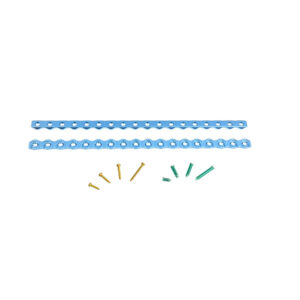
The LYNXVET Rod Locking System is a titanium alloy locking plate system designed for veterinary orthopedic applications. Based on the principles of Biological Osteosynthesis (BO) and angular-stable fixation, the system provides reliable fracture stabilization while minimizing disruption to the local biological environment.
Key Design Principles
- Angular stability — Locking screws engage directly with the plate to form a fixed-angle construct, independent of plate-to-bone compression
- Biological Osteosynthesis (BO) — Preserves periosteal blood supply by eliminating the need for tight plate-to-bone contact
- Minimally invasive application — Low-profile plates allow submuscular insertion with minimal soft tissue stripping
- Versatility — Compatible with both bridging and compression fixation techniques
2. System Overview
2.1 Implant Material
All implants in the LYNXVET Advanced Locking System are manufactured from Titanium Alloy (Ti-6Al-4V), offering:
- High strength-to-weight ratio
- Excellent biocompatibility
- Reduced stress shielding compared to stainless steel
- Minimal imaging artifact on follow-up radiographs
2.2 Plate Specifications
| S/N | Thickness × Width × Length (mm) | Holes | Locking Screw | Cortical Screw | Instrument Set |
| 1 | 1.1 × 3.5 × 136 | 34 | 1.6 mm B-Locking | 1.1 mm Cortical | 1.6 mm Set |
| 2 | 1.5 × 4 × 135 | 30 | 1.6 mm B-Locking | 1.1 mm Cortical | 1.6 mm Set |
| 3 | 1.9 × 5 × 236.5 | 43 | 2.4 mm B-Locking | 1.5 mm Cortical | 2.4 mm Set |
| 4 | 2.1 × 6.5 × 240 | 34 | 2.4 mm B-Locking | 1.5 mm Cortical | 2.4 mm Set |
| 5 | 2.8 × 8 × 234 | 26 | 3.2 mm B-Locking | 2.4 mm Cortical | 3.2 mm Set |
| 6 | 3.1 × 9 × 231 | 22 | 3.2 mm B-Locking | 2.4 mm Cortical | 3.2 mm Set |
| 7 | 4.0 × 10 × 240 | 20 | 4.0 mm B-Locking | 2.7 mm Cortical | 4.0 mm Set |
| 8 | 4.3 × 11 × 234 | 18 | 4.0 mm B-Locking | 2.7 mm Cortical | 4.0 mm Set |
Note: Plates are supplied as full-length reconstruction plates. The surgeon cuts or selects the appropriate number of holes based on patient size and fracture configuration.
2.3 Screw Systems
| System | Locking Screw | Cortical Screw | Recommended Patient Weight |
| 1.6 mm | 1.6 mm B-Locking | 1.1 mm Cortical | < 3 kg (toy breeds, cats) |
| 2.4 mm | 2.4 mm B-Locking | 1.5 mm Cortical | 3–10 kg (small breeds) |
| 3.2 mm | 3.2 mm B-Locking | 2.4 mm Cortical | 10–25 kg (medium breeds) |
| 4.0 mm | 4.0 mm B-Locking | 2.7 mm Cortical | > 25 kg (large breeds) |
3. Indications & Contraindications
3.1 Indications
- Diaphyseal tibial fractures (simple, wedge, or comminuted)
- Metaphyseal tibial fractures
- Tibial fractures with compromised soft tissue coverage
- Revision fixation of failed tibial repairs
- Corrective osteotomies of the tibia
- Fractures in osteopenic bone
3.2 Contraindications
- Active local infection at the surgical site
- Severe systemic illness precluding general anesthesia
- Insufficient bone stock for screw purchase
- Patient non-compliance with postoperative restrictions (relative contraindication)
4. Preoperative Planning
4.1 Radiographic Assessment
Obtain orthogonal radiographic views of the affected limb:
- Craniocaudal (CrCd) view — Assess mediolateral displacement, limb length, and axial alignment
- Mediolateral (ML) view — Assess craniocaudal displacement and rotational deformity
- Contralateral limb — Use as a template for length and angular reference when needed
4.2 Fracture Classification
Classify fractures using the AO/ASIF system to guide fixation strategy:
| AO Type | Description | Recommended Technique |
| Type A (Simple) | Single fracture line, no comminution | Compression or bridging |
| Type B (Wedge) | Butterfly fragment present | Bridging technique |
| Type C (Complex) | Multifragmentary or severely comminuted | Bridging technique |
4.3 Plate and Screw Selection
Select the appropriate system based on patient body weight:
| Body Weight | Recommended System | Plate Dimensions (T × W, mm) |
| < 3 kg | 1.6 mm system | 1.1 × 3.5 or 1.5 × 4 |
| 3–10 kg | 2.4 mm system | 1.9 × 5 or 2.1 × 6.5 |
| 10–25 kg | 3.2 mm system | 2.8 × 8 or 3.1 × 9 |
| > 25 kg | 4.0 mm system | 4.0 × 10 or 4.3 × 11 |
Plate length selection:
- Bridging technique: plate should span 2–3× the length of the fracture zone
- Minimum 3 screws per fragment (proximal and distal to fracture)
4.4 Patient Preparation
- Fast patient for minimum 8–12 hours prior to surgery
- Administer prophylactic antibiotics (cefazolin 22 mg/kg IV) at induction
- Preoperative analgesia: opioid premedication (e.g., methadone 0.2–0.3 mg/kg IM)
- Clip and aseptically prepare the entire affected limb
- Position in lateral recumbency with the affected limb uppermost
5. Surgical Approach
5.1 Standard Medial Approach
1. Make a longitudinal skin incision along the medial aspect of the tibia, centered over the fracture site
2. Incision length should allow adequate visualization: approximately 1.5–2× the plate length for open technique
3. Incise the subcutaneous tissue and deep fascia in line with the skin incision
4. Elevate the periosteum minimally — limit stripping to the immediate fracture zone only
5. Protect the saphenous vein and nerve throughout the approach
5.2 Minimally Invasive Plate Osteosynthesis (MIPO) — Optional
For simple fractures or cases requiring maximum biological preservation:
- Make two small stab incisions: one proximal and one distal to the fracture zone
- Create a submuscular tunnel along the medial tibial surface using a periosteal elevator
- Insert the plate through the tunnel under fluoroscopic guidance
- Confirm plate position with C-arm before screw insertion
6. Fracture Reduction
6.1 Reduction Principles
Follow AO principles of Biological Osteosynthesis (BO):
- Prioritize indirect reduction using ligamentotaxis — restore length, alignment, and rotation without direct manipulation of fracture fragments
- Avoid stripping soft tissue attachments from fracture fragments
- Functional reduction is acceptable for comminuted fractures: correct length and rotation; minor angulation is tolerated
6.2 Reduction Techniques by Fracture Type
| Fracture Type | Reduction Method |
| Transverse (A2) | Manual traction + pointed reduction forceps |
| Oblique (A3) | Reduction forceps applied directly to bone |
| Wedge (B) | Indirect reduction via traction; provisional K-wire |
| Comminuted (C) | Ligamentotaxis; do not attempt anatomic reduction of fragments |
6.3 Reduction Verification
- Palpate fracture ends to confirm cortical alignment
- Confirm under fluoroscopy: axial alignment, limb length, and rotational correction
- Reference the contralateral limb if needed
- Normal canine tibia has approximately 10–15° of physiological cranial bow
7. Plate Selection
7.1 Choosing the Correct Plate Profile
| Fracture Location | Recommended Plate | Notes |
| Proximal tibia | Wider profile (2.1 × 6.5 or 3.1 × 9) | More holes for metaphyseal fixation |
| Tibial diaphysis | Standard profile | Bridging or compression |
| Distal tibia | Narrower profile with bullet tip | Facilitates submuscular insertion |
7.2 Plate Length
- Count the number of holes needed: minimum 3 holes per fragment
- For bridging: leave 2–4 holes empty over the fracture zone
- Longer plates with fewer screws are preferred over short plates with maximum screws (BO principle)
7.3 Clinical Example
Patient: 20 kg Labrador Retriever, mid-diaphyseal comminuted tibial fracture
- System: 3.2 mm (2.8 × 8 mm plate)
- Plate length: 8–10 holes
- Screw plan: 3 locking screws proximal, 3 locking screws distal, fracture zone unbridged
8. Plate Application & Provisional Fixation
Step 1 — Plate Contouring (if required)
- The LYNXVET Advanced Locking System plates are supplied as straight reconstruction plates
- Use the Bender instrument to contour the plate to match the tibial surface if needed
- Avoid repeated bending at the same point to prevent metal fatigue
- Do not bend through screw holes
Step 2 — Plate Positioning
- Place the plate on the medial or craniomedial surface of the tibia
- Ensure the plate longitudinal axis is parallel to the tibial mechanical axis
- Confirm plate position under fluoroscopy in both planes
Step 3 — Provisional Fixation
- Insert a 1.0–1.5 mm K-wire through the most proximal and most distal plate holes to temporarily secure the plate
- Alternatively, insert one cortical screw in compression mode to hold the plate while locking screws are placed
- Re-confirm fracture reduction and plate position under fluoroscopy before final fixation
9. Screw Insertion
9.1 Screw Type Selection
| Fixation Goal | Screw Type | Technique |
| Angular-stable fixation | B-Locking Screw | Insert through Locking Drill Guide |
| Interfragmentary compression | Cortical Screw | Insert through standard Drill Guide |
| Lag screw effect | Cortical Screw | Overdrill near cortex |
9.2 Locking Screw Insertion — Step by Step
Step 1: Attach the Locking Drill Guide
- Thread the Locking Drill Guide into the plate hole
- Ensures the drill trajectory is perpendicular to the plate, engaging the locking thread correctly
Step 2: Drill
- Use the appropriate AO Drill Bit for the selected screw system
- Drill through both cortices under controlled speed
- Irrigate with saline to prevent thermal necrosis
Step 3: Measure Screw Length
- Insert the Depth Gauge through the drill hole
- Select a screw 1–2 mm shorter than the measured depth to avoid cortical protrusion
Step 4: Insert Locking Screw
- Attach the AO Screwdriver to the QC Screwdriver Handle
- Drive the B-Locking Screw until it engages the plate thread
- Do not overtighten — the locking mechanism is complete when the screw head is flush with the plate
9.3 Screw Distribution Strategy
Bridging Technique (comminuted fractures):
| Proximal: | L | L | L | |||||
| fracture | zone | |||||||
| Distal: | L | L | L |
| Symbol | Meaning |
| L (blue) | Locking screw — fixed-angle fixation |
| (grey) | Empty hole — no screw placed (bridging zone) |
Compression Technique (simple transverse fractures):
| L | L | C | C | L | L | |
| fracture | line |
| Symbol | Meaning |
| L (dark blue) | Locking screw — fixed-angle fixation |
| C (blue) | Cortical screw — interfragmentary compression |
9.4 Final Verification
- Fluoroscopic confirmation of all screw positions and lengths in two planes
- Confirm fracture reduction is maintained
- Check for any plate lift-off or deformation
- Remove provisional K-wires if used
10. Wound Closure
1. Irrigate the surgical site copiously with sterile saline
2. Close the deep fascia with absorbable suture (e.g., 2-0 or 3-0 PDS) in a simple continuous pattern
3. Close subcutaneous tissue with absorbable suture
4. Close skin with non-absorbable suture (e.g., 3-0 nylon) in interrupted pattern, or use skin staples
5. Apply a light compressive bandage for 24–48 hours postoperatively
11. Postoperative Management
11.1 Acute Phase (Days 0–14)
Pain Management:
- Meloxicam 0.1 mg/kg SID PO for 5–7 days
- Tramadol 2–5 mg/kg BID–TID PO for 3–5 days if needed
- Gabapentin for neuropathic pain component if indicated
Wound Care:
- Inspect incision daily for signs of swelling, discharge, or dehiscence
- Suture/staple removal at 10–14 days
- Use Elizabethan collar to prevent self-trauma
11.2 Rehabilitation Protocol
| Postoperative Week | Activity Level |
| 0–2 | Strict rest; leash walks for toileting only (5 min max) |
| 2–4 | Short controlled leash walks (10–15 min, 2–3×/day) |
| 4–6 | Gradual increase in walk duration; no running or jumping |
| 6–8 | Return to normal activity based on radiographic healing |
11.3 Follow-Up Radiographs
| Timepoint | Purpose |
| 4 weeks postop | Assess early callus formation; confirm implant position |
| 8 weeks postop | Confirm bridging callus; evaluate for full weight-bearing |
| 12 weeks postop | Final healing assessment; consider implant removal if indicated |
11.4 Healing Criteria
Clinical healing:
- Full weight-bearing without pain
- No crepitus at fracture site
- Normal range of motion
Radiographic healing:
- Obliteration of fracture line
- Continuous bridging callus on ≥ 2 cortices
- No radiolucency at plate-bone interface
12. Implant Removal
12.1 Indications for Removal
- Confirmed radiographic and clinical healing
- Implant-associated infection or persistent drainage
- Implant loosening or mechanical failure
- Young, growing animals (to prevent growth disturbance)
- Owner request after confirmed healing
12.2 Timing
- Routine removal: 6–12 months postoperatively
- Skeletally immature patients: after physeal closure
- Infected implants: as soon as infection is controlled
12.3 Removal Technique
1. Approach via the original incision
2. Identify and protect adjacent neurovascular structures
3. Remove screws individually using the AO Screwdriver and QC Screwdriver Handle
4. For stripped screws, use a screw extraction kit
5. Slide the plate free from the periosteal surface
6. Close in layers as described in Section 10
13. Complications & Management
13.1 Early Complications
| Complication | Signs | Management |
| Surgical site infection | Swelling, discharge, pyrexia | Culture and sensitivity; systemic antibiotics; debridement if needed |
| Hematoma | Localized swelling, pain | Compressive bandage; aspiration if large |
| Nerve injury | Sensory or motor deficit | Neuroprotective support; monitor for recovery |
| Implant malpositioning | Abnormal radiographic appearance | Revision surgery if clinically significant |
13.2 Late Complications
| Complication | Signs | Management |
| Delayed union | No callus at 8 weeks | Restrict activity; nutritional support; consider bone grafting |
| Non-union | Persistent fracture line > 16 weeks | Revision fixation + autogenous bone graft |
| Implant loosening | Screw back-out, plate deformation | Revision fixation |
| Implant fatigue failure | Plate or screw fracture | Revision fixation |
| Joint stiffness | Reduced range of motion | Physiotherapy; passive range of motion exercises |
13.3 Prevention
- Strict aseptic technique throughout
- Adhere to biological fixation principles — avoid unnecessary periosteal stripping
- Select implant size appropriate for patient weight and activity level
- Enforce postoperative activity restriction
- Schedule regular follow-up radiographs
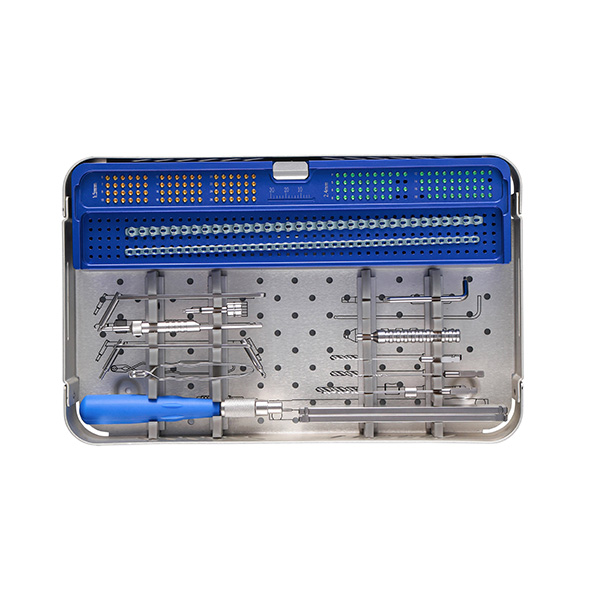
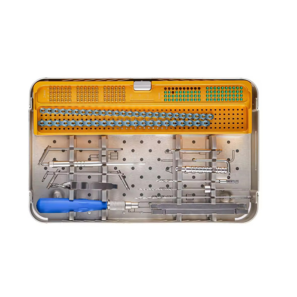
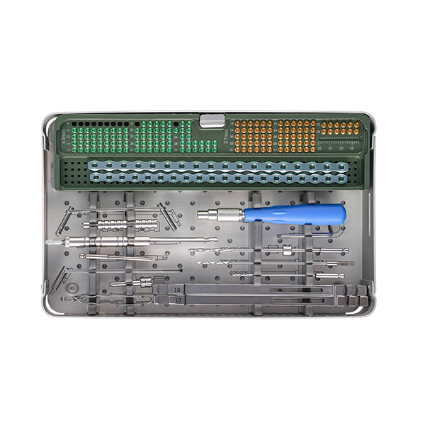
14. Instrument Set
The following instruments are included in the LYNXVET Advanced Locking System instrument set:
| Instrument | Function |
| AO Screwdriver | Drives locking and cortical screws into bone |
| AO Drill Bit | Prepares pilot holes for locking screws (system-specific diameter) |
| AO Drill Bit | Prepares pilot holes for cortical screws (system-specific diameter) |
| QC Screwdriver Handle | Quick-connect handle for AO Screwdriver; provides torque control |
| Drill Guide | Guides drill bit for cortical screw insertion; protects soft tissue |
| Depth Gauge | Measures screw length after drilling |
| Bender | Contours the plate to match bone surface if required |
| Locking Drill Guide | Threads into plate hole to ensure correct drill trajectory for locking screw engagement |
15. Product Specifications
15.1 Reconstruction Plates — Full Specifications
| S/N | Thickness × Width × Length (mm) | Holes | Locking Screw | Cortical Screw | Instrument Set |
| 1 | 1.1 × 3.5 × 136 | 34 | 1.6 mm B-Locking | 1.1 mm Cortical | ALS Set – 1.6 mm |
| 2 | 1.5 × 4 × 135 | 30 | 1.6 mm B-Locking | 1.1 mm Cortical | ALS Set – 1.6 mm |
| 3 | 1.9 × 5 × 236.5 | 43 | 2.4 mm B-Locking | 1.5 mm Cortical | ALS Set – 2.4 mm |
| 4 | 2.1 × 6.5 × 240 | 34 | 2.4 mm B-Locking | 1.5 mm Cortical | ALS Set – 2.4 mm |
| 5 | 2.8 × 8 × 234 | 26 | 3.2 mm B-Locking | 2.4 mm Cortical | ALS Set – 3.2 mm |
| 6 | 3.1 × 9 × 231 | 22 | 3.2 mm B-Locking | 2.4 mm Cortical | ALS Set – 3.2 mm |
| 7 | 4.0 × 10 × 240 | 20 | 4.0 mm B-Locking | 2.7 mm Cortical | ALS Set – 4.0 mm |
| 8 | 4.3 × 11 × 234 | 18 | 4.0 mm B-Locking | 2.7 mm Cortical | ALS Set – 4.0 mm |
15.2 Material
All implants: Titanium Alloy (Ti-6Al-4V)
15.3 Contact & Ordering
- Website: www.lynxvetortho.com
- Email: sales@lynxvetortho.com
- WhatsApp: +86 189 6113 9089
- Address: D813, Taihu Road 9-4, Xinbei District, Changzhou, Jiangsu, China
References
- Johnson AL, Houlton JEF, Vannini R. AO Principles of Animal Osteosynthesis. 2nd Edition. AO Publishing.
- Piermattei DL, Flo GL, DeCamp CE. Handbook of Small Animal Orthopedics and Fracture Repair. 4th Edition. Saunders.
- Ruedi TP, Buckley RE, Moran CG. AO Principles of Fracture Management. 2nd Edition. Thieme.
- Perren SM. Evolution of the internal fixation of long bone fractures. J Bone Joint Surg Br. 2002;84(8):1093–1110.
- Gautier E, Sommer C. Guidelines for the clinical application of the LCP. Injury. 2003;34(Suppl 2):B63–76.
Disclaimer
This guide is intended for educational purposes only. It describes the surgical technique for the LYNXVET Advanced Locking System in veterinary orthopedic applications. Clinical decisions should always be based on individual patient assessment and the surgeon’s professional judgment. LYNXVET Orthopedics assumes no liability for clinical outcomes resulting from the use of techniques described herein.